Special thanks to Mega Satish for her meaningful contributions, support, and wisdom that helped shape this work.
The project’s main goal is to build an online book store where users can search for and buy books based on title, author, and subject. The chosen books are shown in a tabular style and the customer may buy them online using a credit card. Using this Website, the user may buy a book online rather than going to a bookshop and spending time. Many online bookstores, such as Powell’s and Amazon, were created using HTML. We suggest creating a comparable website with .NET and SQL Server. An online book store is a web application that allows customers to purchase ebooks. Through a web browser the customers can search for a book by its title or author, later can add it to the shopping cart and finally purchase using a credit card transaction. The client may sign in using his login credentials, or new clients can simply open an account. Customers must submit their full name, contact details, and shipping address. The user may also provide a review of a book by rating it on a scale of one to five. The books are classified into different types depending on their subject matter, such as software, databases, English, and architecture. Customers can shop online at the Online Book Store Website using a web browser. A client may create an account, sign in, add things to his shopping basket, and buy the product using his credit card information. As opposed to a frequent user, the Administrator has more abilities. He has the ability to add, delete, and edit book details, book categories, and member information, as well as confirm a placed order. This application was created with PHP and web programming languages. The Online Book Store is built using the Master page, data sets, data grids, and user controls.
Introduction
Problem Statement
The software to be designed is for a bookstore that wishes to go online. lt is to be developed to improve the efficiency for the customer. The important features to be developed include:
- The Login/Registration module requires the customer to login into the system or he can create an account if he does not yet have one.
- Order module requires a customer to enter the book details that he/she wants to buy.
- Book detail(s) module allows the system to keep book information in detail by name, genre etc.
- Stock management will tell you about the number of books left in the store.
- Payment module allows the customer to make online payments like Paytm and credit/debit cards or cash on delivery.
- Delivery and tracking module gives information about tracking and by whom it is delivered.
- User feedback module.
Purpose And Motivation
The main objective of the project is to create an online book store that allows users to search and purchase a book based on the title, author and subject. The selected books are displayed in a tabular format and the user can order their books online through credit card payment. The Administrator will have additional functionalities when compared to the common user.
The motivation to create this project has many sources:
- Interest to develop a good user-friendly website with many online transactions using a database.
- To increase my knowledge horizon in technologies like .NET, SQL, CSS, HTML.
- To gain good experience in .NET before joining a full-time job.
- To gain expertise using Data Grid, Data Set, Data Table, Data Adapter and Data Readers.
Process Model
Process Model
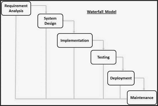
We choose the WATERFALL MODEL due to the following reasons:
- This model is chosen because our requirements are very well known, clear and fixed.
- Product definition is stable.
- There are no ambiguous requirements in our project.
- The project is short.
- This model is simple and easy to understand and use.
- It is easy to manage due to the rigidity of the model – each phase has specific deliverables and a review process.
- In this model, phases are processed and completed one at a time. Phases do not overlap.
- Waterfall model works well for smaller projects where requirements are very well understood.
First of all the feasibility study is done. Once that part is over the requirement analysis and project planning begins. After the requirements study is done, the design process begins, followed by the coding process. Once the programming is completed the testing is done.
In this model, the sequence of activities performed in a software development project are:
- Requirement Analysis
- Project Planning
- System design
- Detail design
- Coding
- Unit testing
- System integration & testing
Here the linear ordering of these activities is critical. End of the phase and the output of one phase is the input of another phase. The output of each phase is to be consistent with the overall requirement of the system. Some of the qualities of the spiral model are also incorporated after the people concerned with the project review completion of each of the phases of the work done.
WATERFALL MODEL was chosen because all requirements were known beforehand and the objective of our software development is the computerization/automation of an already existing manual working system.
Data Flow Diagram (DFD)
The data flow diagram is a graphical representation of the flow of data in an information system. It is capable of depicting incoming data flow, outgoing data flow and stored data. The DFD does not mention anything about how data flows through the system. There is a prominent difference between DFD and Flowchart. The flowchart depicts a flow of control in program modules. DFDs depict the flow of data in the system at various levels. DFD does not contain any control or branch elements.
Zero Level Data flow Diagram (0 Level DFD) of Digital Bookstore
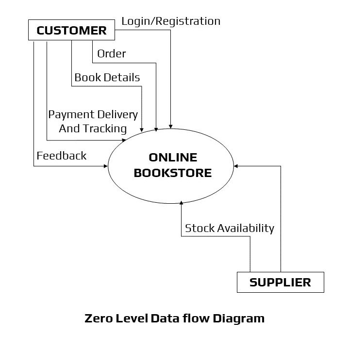
Zero Level DFD
First Level Data flow Diagram (1 Level DFD) of Digital Bookstore
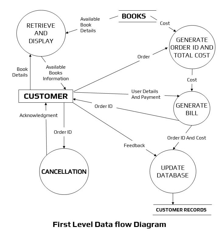
First Level DFD
Second Level Data flow Diagram (2 Level DFD) of Digital Bookstore
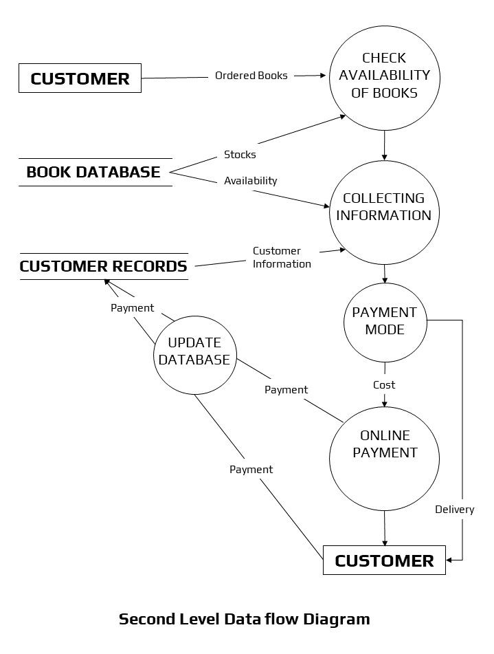
Second Level DFD
Class Diagram
The class diagram is a static diagram. It represents the static view of an application. The class diagram is not only used for visualizing, describing, and documenting different aspects of a system but also for constructing executable code of the software application. The class diagram describes the attributes and operations of a class and also the constraints imposed on the system. Since they’re the only UML diagrams that can be translated directly to object-oriented languages, class diagrams are frequently utilised in the designing of object-oriented systems. The class diagram shows a collection of classes, interfaces, associations, collaborations, and constraints.
Purpose of Class Diagram
The class diagram is used to represent the basic perspective of a system. Class diagrams are the only designs that can be highly associated with object-oriented languages and are thus generally applied throughout development. UML diagrams like activity diagrams, sequence diagrams can only give the sequence flow of the application, however, the class diagram is a bit different. That’s the most widely used UML diagram in the computing world.
The class diagram’s aim may be described as:
- Design and development of a software’s static view.
- Describe the responsibilities of a system.
- The base for component and deployment diagrams.
- Forward and reverse engineering.
UML class diagrams are useful when modelling business data. By accurately modelling attributes and associations of class entities, we can easily map these class diagram specifications to entity beans with CMP. Class attributes map to abstract access methods for persistent fields, and association roles map to abstract access methods for relationship fields. Navigability determines whether relationship access methods appear in both related entity beans or just one. Furthermore, multiplicity notation determines the correct type for relationship fields, life cycle issues, and cascading delete characteristics.
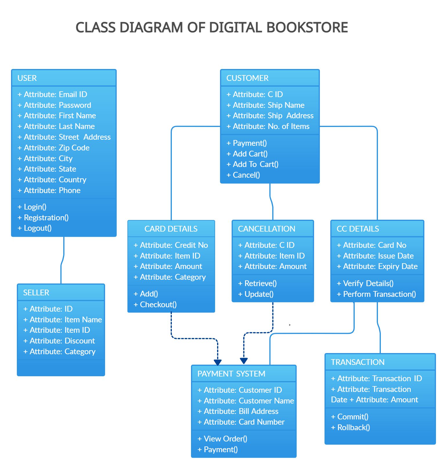
Class Diagram
Sequence Diagram
The sequence diagram represents the flow of messages in the system and is also termed an event diagram. It helps in envisioning several dynamic scenarios. It portrays the communication between any two lifelines as a time-ordered sequence of events, such that these lifelines took part at the run time. In UML, the lifeline is represented by a vertical bar, whereas the message flow is represented by a vertical dotted line that extends across the bottom of the page. It incorporates the iterations as well as branching.
Purpose of Sequence Diagram
- To model high-level interaction among active objects within a system.
- To model interaction among objects inside a collaboration realizing a use case.
- It either models generic interactions or some certain instances of interaction.
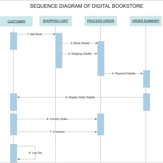
Sequence Diagram
Collaboration Diagram
The collaboration diagram is used to show the relationship between the objects in a system. Both the sequence and the collaboration diagrams represent the same information but differently. Instead of showing the flow of messages, it depicts the architecture of the object residing in the system as it is based on object-oriented programming. An object consists of several features. Multiple objects present in the system are connected to each other. The collaboration diagram, which is also known as a communication diagram, is used to portray the object’s architecture in the system.
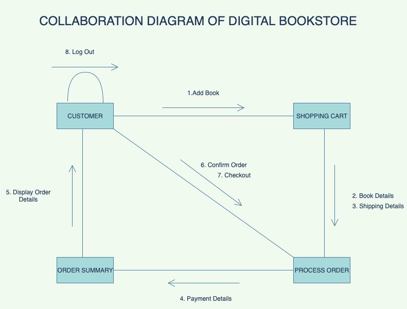
Collaboration Diagram
Statechart Diagram
A state-chart diagram depicts the various modes of an element in a system. The stages are unique to a system component or item. A state machine is depicted by a Statechart diagram. A state machine is a device that specifies distinct states of an item and controls these states through explicit or implicit events.
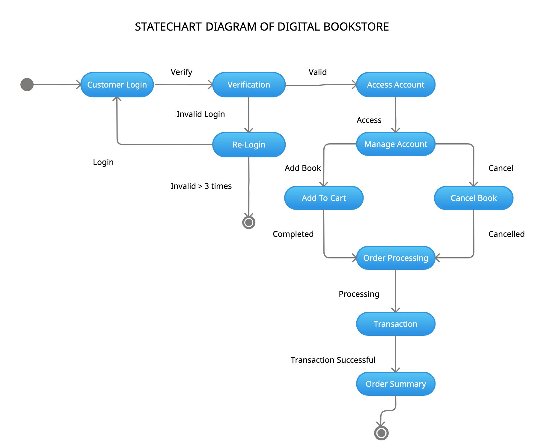
Statechart Diagram
Activity Diagram
Another essential diagram in UML for describing the dynamic features of the system is the activity diagram. It is essentially a flowchart that represents the transition from one activity to another. The action can be defined as a system operation. The control flow is directed from one activity to the next. This flow might be linear, branching, or parallel in nature.
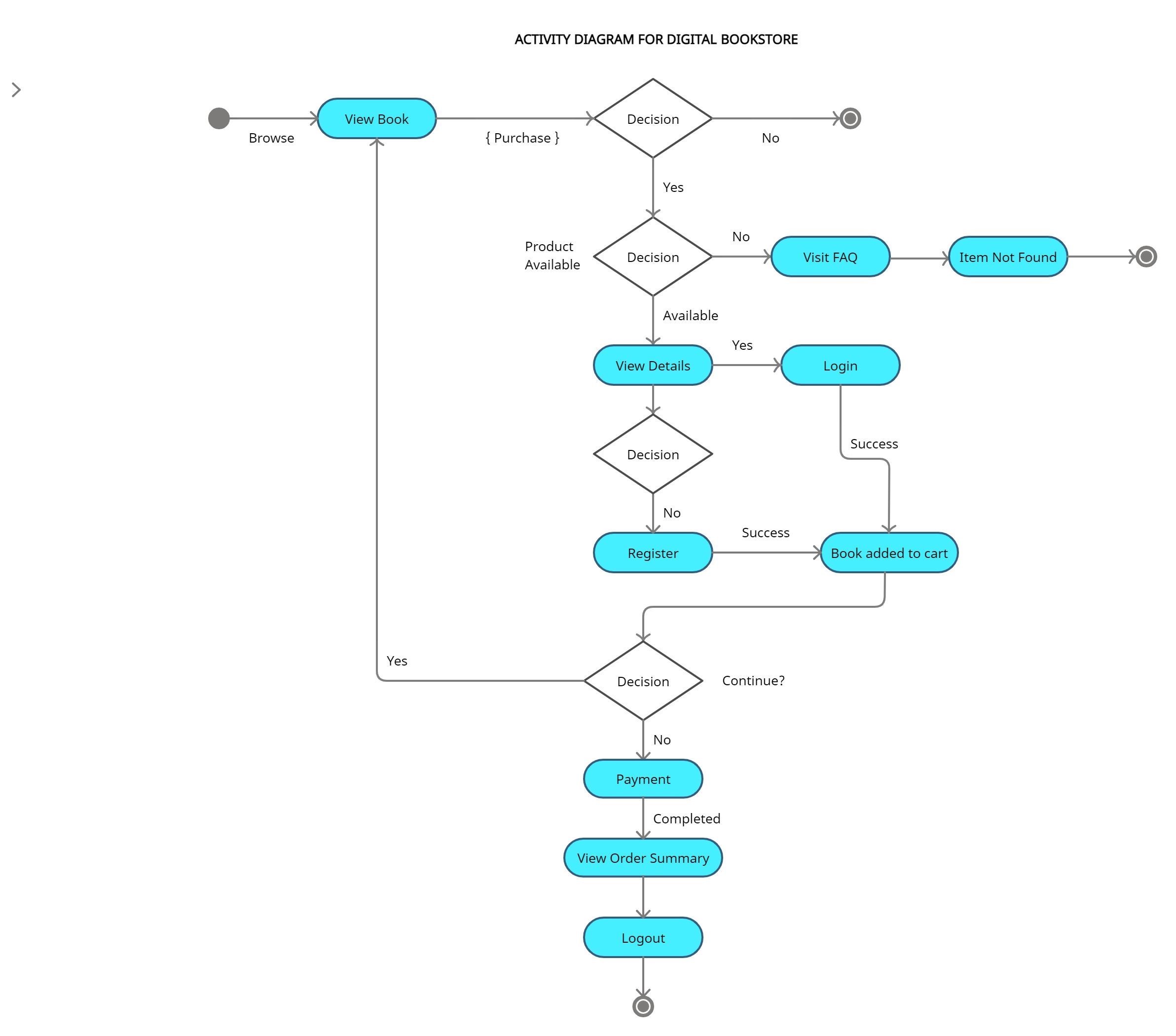
Activity Diagram
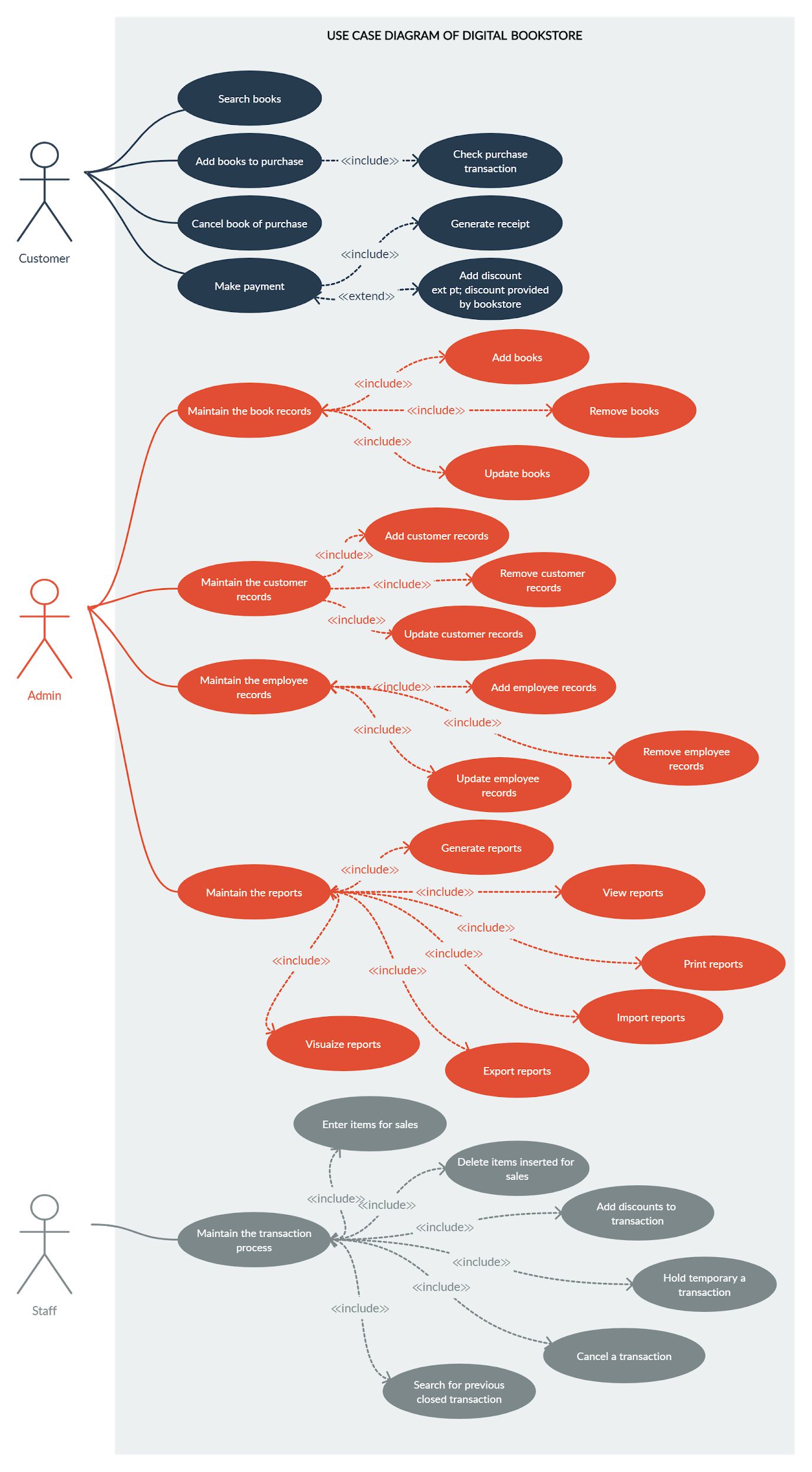
Use Case Diagram
A UML use case diagram is the principal form of system/software specifications for an undeveloped computer program. Use cases specify the expected behaviour (what), and not the exact method of making it happen (how). Use cases once specified can be denoted by both textual and visual representation (i.e. use case diagram). A key concept of use case modelling is that it helps us design a system from the end user’s perspective. It is an effective technique for communicating system behaviour in the user’s terms by specifying all externally visible system behaviour.
A use case diagram is usually simple. It does not show the detail of the use cases:
- It only outlines several of the connections between use cases, actors, and systems.
- It does not show the order in which steps are performed to achieve the goals of each use case.
Use Case Diagram
Gantt Chart
A Gantt chart is a typical bar chart that is used in project management to visually depict the progress of a development plan across time. Contemporary Gantt charts generally indicate the timetable and status of each job in the task, as well as who is accountable for them.
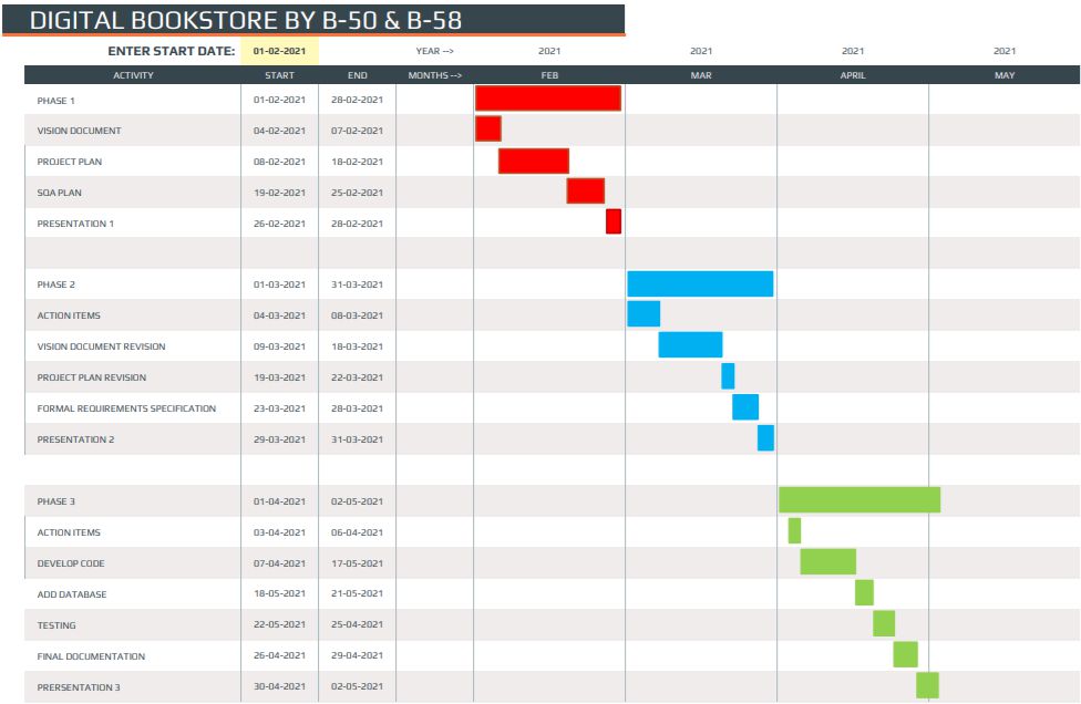
Gantt Chart
Database
Database Connectivity
<?php
define('DB_HOST', 'localhost');
define('DB_NAME', 'digital_bookstore');
define('DB_USER','root');
define('DB_PASSWORD','');
$con=mysqli_connect(DB_HOST,DB_USER,DB_PASSWORD) or die("Failed to connect to MySQL: " . mysql_error());
$db=mysqli_select_db($con,DB_NAME) or die("Failed to connect to MySQL: " . mysql_error());
?>
Database
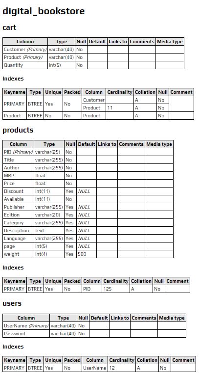
Database Tables
Testing
We performed White Box Testing (Basis Path Testing) on a function of Online Bookstore and developed the test cases for the same.
Function (Login Function)
//login function//
Function submit()
{
    $username=$_POST['login_username'];
    $password=$_POST['login_password'];
    $query = "SELECT * from users where UserName = '$username' AND Password = '$password'";
    $result = mysqli_query($con,$query) or die(mysql_error());
    if(mysqli_num_rows($result) > 0)
    {
        $row = mysqli_fetch_assoc($result);
        $_SESSION['user']=$row['UserName'];
        header("Location: index.php?login=" . "Successfully Logged In");
    }
    else
        echo "Incorrect username or password";
}
Flow Graph
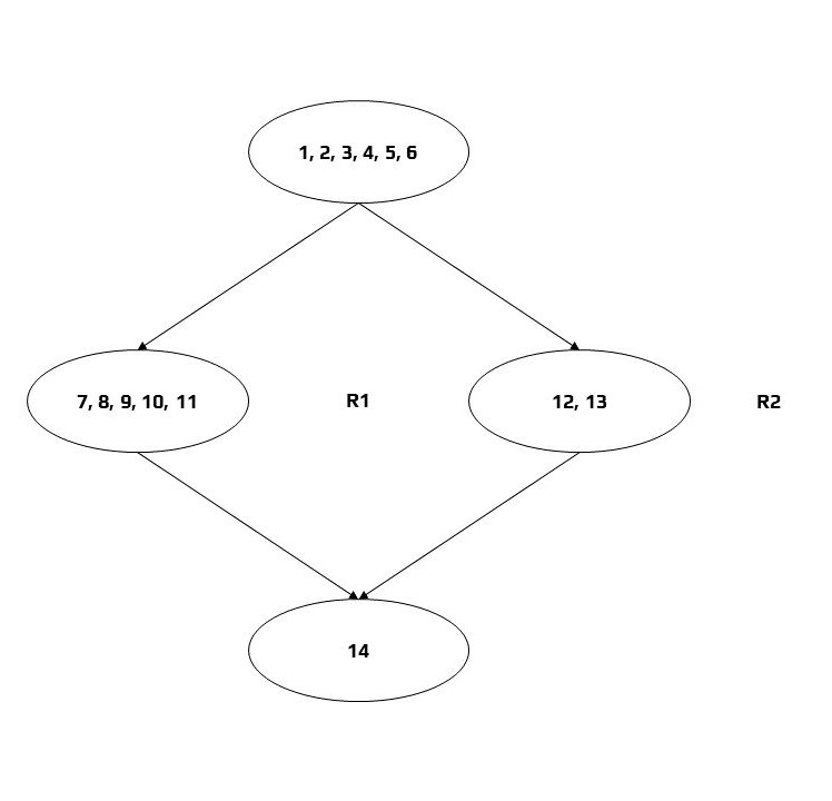
Flow Graph
Independent Paths
Path 1: 1 → 2 → 3 → 4 → 5 → 6 → 7 → 8 → 9 → 10 → 11 → 14
Path 2: 1 → 2 → 3 → 4 → 5 → 6 → 12 → 13 → 14
Cyclomatic Complexity
- Method 1:
In the above control flow graph, where, e = 4 and n = 4
Therefore, Cyclomatic Complexity
V(G) = 4 – 4 + 2 = 2
- Method 2:
In the above control flow graph, where, P = 1
Therefore, Cyclomatic Complexity
V(G) = 1 + 1 = 2
- Method 3:
In the above control flow graph, there are 2 regions
Test Cases
Table 1: Test Cases
| Test Case ID | Input Number | Output | Independent Path Covered |
|---|---|---|---|
| 1 | 1 | Login | 1 → 2 → 3 → 4 → 5 → 6 → 7 → 8 → 9 → 10 → 11 → 14 |
| 2 | 0 | No Login | 1 → 2 → 3 → 4 → 5 → 6 → 12 → 13 → 14 |
YouTube Demonstration
Conclusion
The transition from buying written books in bookshops to ordering them online or even simply digital versions has had a significant impact on the industry, including retailers and libraries, as well as the general public throughout the globe. We present an application developed using software engineering methodologies. Digital Bookstore allows the users to buy as well as review books online. Consumers can login and search for their books, whether it is available or out of stock. Users can also give feedback. We have implemented and tested the web application to satisfy the user specifications.
Additional Resources
Project Source & Study Materials
Access the complete source code for this Digital Bookstore project, research paper, preprint, lecture notes, and related Database Management System (DBMS) study materials via the links below:
Citation
Please cite this work as:
Thakur, Amey. "Digital Bookstore". AmeyArc (Jul 2021). https://amey-thakur.github.io/posts/2021-07-17-digital-bookstore/.Or use the BibTex citation:
@article{thakur2021bookstore,
  title   = "Digital Bookstore",
  author  = "Thakur, Amey",
  journal = "amey-thakur.github.io",
  year    = "2021",
  month   = "Jul",
  url     = "https://amey-thakur.github.io/posts/2021-07-17-digital-bookstore/"
}